Overview
PWM servos are controlled using Pulse Width Modulation signals to adjust their position or speed. They are widely used in robotics, RC models, and electronics projects. For detailed specifications and code examples, refer to the specific servo pages such as SG90, MG90S, and MG996R.
Quick Navigation
Code Examples
[

Arduino
C++ Framework
](#arduino)[

ESP-IDF
Native Framework
](#esp-idf)[

ESPHome
YAML Configuration
](#esphome)[

PlatformIO
IDE & Toolchain
](#platformio)[

MicroPython
Python Framework ](#micropython)
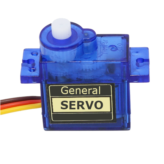
About General Servo
PWM servos are versatile motors commonly used in robotics. They operate based on Pulse Width Modulation (PWM) signals to control the position or speed of the servo arm.
Technical Specifications (Stall Current)
Stall current is the maximum current drawn when the motor is blocked or starts moving under load. Ensure your power supply can handle these peaks to avoid microcontroller resets.
| Model | Operating Voltage | Stall Current (Peak) | Gear Type |
|---|---|---|---|
| SG90 | 4.8V - 6.0V | ~650 mA | Nylon |
| MG90S | 4.8V - 6.0V | ~800 mA | Metal |
| MG996R | 4.8V - 7.2V | ~1400 - 2500 mA | Metal |
Analog vs Digital Servos
The main difference lies in how they process the PWM signal:
- Analog Servos: Use standard 50Hz PWM frequency. They update motor power only when a new pulse arrives (every 20ms).
- Digital Servos: Can handle higher PWM frequencies (up to 300Hz+). They use a high-speed microprocessor to update motor power much more frequently, resulting in faster response, smoother movement, and significantly higher holding torque.
360-Degree Servos (Continuous Rotation)
Unlike standard servos that move to a specific angle (0-180°), 360-degree models rotate continuously.
- Control: The PWM signal controls speed and direction instead of position.
- Neutral Point: A 1500µs (usually 90°) pulse stops the motor.
- Operation: Pulses < 1500µs rotate the motor CCW, pulses > 1500µs rotate it CW. The further the value from the neutral point, the faster the rotation.
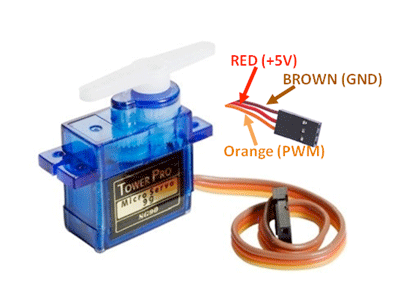
Pinout
General PWM servos have 3 wires: GND (brown/black), VCC (red), and DATA/Signal (orange/yellow/white).
| Pin | Name | Type | Description |
|---|---|---|---|
| 1 | GND | Power | Ground connection. Connect to MCU and Power Supply GND. |
| 2 | VCC | Power | Power supply (typically 4.8V-6V). |
| 3 | Signal | PWM | PWM control signal (50Hz, 1-2ms pulse width). |
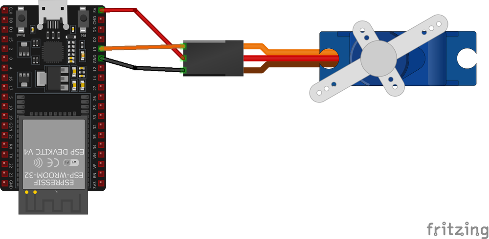
Wiring & Connection Guide
Capacitor Instruction
Servos create significant electrical noise and sudden current draws that can cause your microcontroller (ESP32/Arduino) to reset.
Recommendation: Connect an electrolytic capacitor (e.g., 470µF to 1000µF, 10V or higher) across the VCC and GND lines as close to the servo as possible.
- Why: It acts as a buffer, providing instant power during peak draws and smoothing out voltage spikes.
- Polarity: Ensure the negative lead (shorter, marked with a stripe) goes to GND and the positive lead to VCC.
Code Examples
Arduino: Smooth Sweep (Non-blocking)
This example uses millis() instead of delay() to allow the microcontroller to perform other tasks while the servo moves smoothly.
#include <Servo.h>

Servo myServo;
unsigned long lastMoveTime = 0;
int currentPos = 0;
int step = 1;
const int interval = 15; // Time between steps in ms

void setup() {
  myServo.attach(9); // Attach to pin 9
}

void loop() {
  unsigned long currentTime = millis();

  if (currentTime - lastMoveTime >= interval) {
    lastMoveTime = currentTime;

    currentPos += step;
    if (currentPos <= 0 || currentPos >= 180) {
      step = -step; // Reverse direction at limits
    }

    myServo.write(currentPos);
  }

  // You can run other code here without blocking!
}
ESP-IDF Example
#include "driver/ledc.h"
#include "esp_err.h"

#define SERVO_PIN GPIO_NUM_18
#define SERVO_MIN_PULSEWIDTH 500
#define SERVO_MAX_PULSEWIDTH 2500
#define SERVO_MAX_DEGREE 180

uint32_t calculate_pulse_width(uint32_t angle) {
    return SERVO_MIN_PULSEWIDTH + ((SERVO_MAX_PULSEWIDTH - SERVO_MIN_PULSEWIDTH) * angle) / SERVO_MAX_DEGREE;
}

void app_main() {
    ledc_timer_config_t ledc_timer = {
        .speed_mode = LEDC_LOW_SPEED_MODE,
        .timer_num = LEDC_TIMER_0,
        .duty_resolution = LEDC_TIMER_16_BIT,
        .freq_hz = 50,
        .clk_cfg = LEDC_AUTO_CLK
    };
    ledc_timer_config(&ledc_timer);

    ledc_channel_config_t ledc_channel = {
        .speed_mode = LEDC_LOW_SPEED_MODE,
        .channel = LEDC_CHANNEL_0,
        .timer_sel = LEDC_TIMER_0,
        .intr_type = LEDC_INTR_DISABLE,
        .gpio_num = SERVO_PIN,
        .duty = 0,
        .hpoint = 0
    };
    ledc_channel_config(&ledc_channel);

    while (1) {
        uint32_t duty = calculate_pulse_width(0);
        ledc_set_duty(LEDC_LOW_SPEED_MODE, LEDC_CHANNEL_0, duty);
        ledc_update_duty(LEDC_LOW_SPEED_MODE, LEDC_CHANNEL_0);
        vTaskDelay(pdMS_TO_TICKS(1000));

        duty = calculate_pulse_width(90);
        ledc_set_duty(LEDC_LOW_SPEED_MODE, LEDC_CHANNEL_0, duty);
        ledc_update_duty(LEDC_LOW_SPEED_MODE, LEDC_CHANNEL_0);
        vTaskDelay(pdMS_TO_TICKS(1000));
    }
}
MicroPython Example
from machine import Pin, PWM
from time import sleep

servo = PWM(Pin(18))
servo.freq(50)

def set_servo_angle(angle):
    # Duty cycle range: approx 40 to 115 for 0-180 degrees
    duty = int(40 + (angle / 180) * 115)
    servo.duty(duty)

while True:
    set_servo_angle(0)
    sleep(1)
    set_servo_angle(180)
    sleep(1)
Troubleshooting
- Jittering: Ensure common ground between MCU and external power supply. Check if the power supply can provide enough current (see stall current table).
- Resets: Add the recommended capacitor and use a separate power source for servos.
- Wrong Range: Some servos use 500-2500µs timing instead of 1000-2000µs. Adjust your PWM limits if you can’t reach full 180°.
Explore Alternative Sensors
PCA9685 16-Channel Driver
Ideal for controlling up to 16 servos using only 2 pins (I2C).
MG996R High Torque
Heavy-duty metal gear servo for loads up to 11 kg·cm.
MG90S Mini Servo
The “gold standard” micro servo with metal gears for durability.